Technical introduction
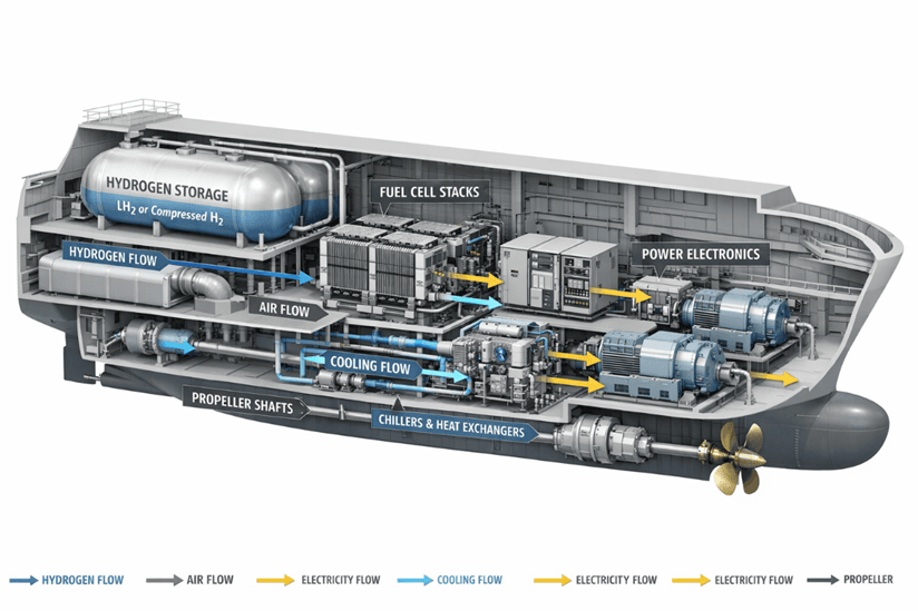
The decarbonization of shipping is facing a fundamental system conflict: the range and availability of fossil fuels are coming up against increasingly stringent emission requirements. Battery-electric solutions for ocean-going vessels generally fail due to volume, mass and charging time limits. Hydrogen-based systems therefore appear attractive - provided that the overall system comprising storage, conditioning, fuel cell, cooling, power electronics and safety concept can be sensibly integrated.
In practice, however, the stack alone is not decisive. The effects on weight, installation space, center of gravity, trim, maintainability, accessibility and redundancy architecture are decisive. This is precisely where a „record stack“ becomes technically relevant - or, in the worst case, an isolated technology demonstration without systemic connectivity.
Technology classification
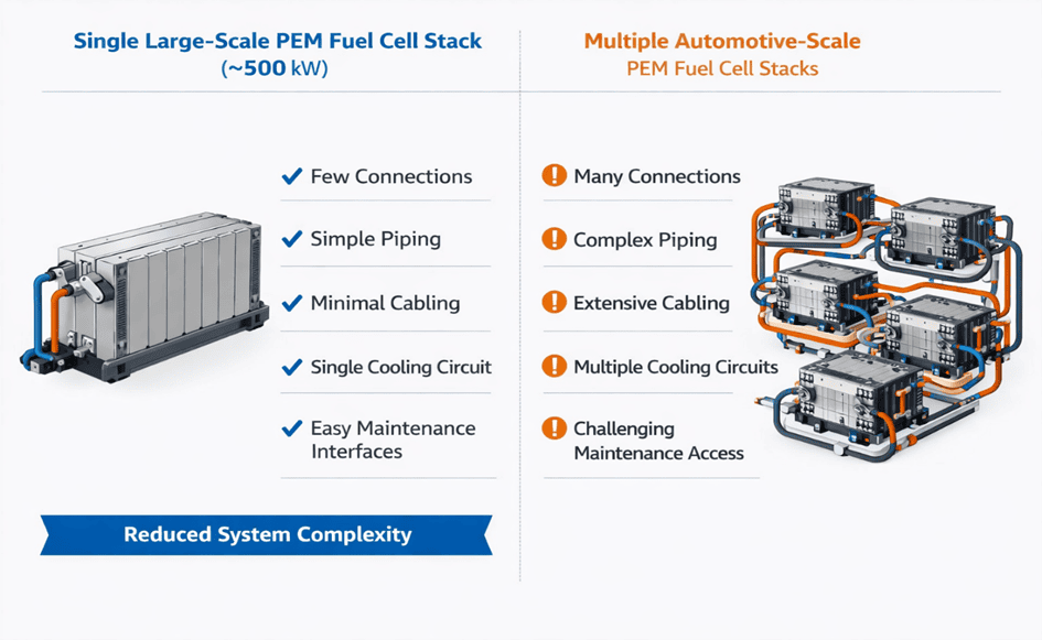
The Center for Solar Energy and Hydrogen Research Baden-Württemberg (ZSW) reports on what it claims is the world's largest PEM fuel cell stack for maritime applications, which was successfully tested in Ulm. The approach: instead of many small automotive stacks (typically 1,300 cm² (automotive typically 300-500 cm²). This allows a single stack to reach around the 500 kW class and is intended to reduce system complexity (wiring, cooling circuits, cabling, maintenance).
Another technical aspect is the choice of bipolar plate material: for large-format plates, ZSW relies on graphite-based bipolar plates, arguing that stainless steel is difficult to produce flat and dimensionally stable in large formats; graphite remains dimensionally stable, but tends to be thicker and heavier.
Engineering interpretation
From a system perspective, ZSW addresses a classic integration lever: reducing complexity by reducing parallel power paths. In maritime propulsion or on-board energy systems, each additional stack typically means:
- Additional media connections (H₂, air/O₂, coolant),
- additional sensors and safety chains,
- additional DC power paths, contactors and cable routes,
- additional maintenance interfaces and spare parts variants.
A 500 kW stack shifts the architectural decision: Fewer stacks deliver the same power. This is fundamentally advantageous in terms of reliability, cabling, packaging and costs. At the same time, scaling over larger cell areas brings new boundary conditions: Sealing concepts, flatness tolerances, uniform gas distribution over large areas, local hotspots and mechanical stresses in the stack structure.
The „record“ is therefore not so much an end in itself, but a step towards shifting the technical scaling limit (surface area, material, production) into an industrially relevant area.
Lightweight construction analysis
1. system effects
Local mass vs. system mass:
Switching from stainless steel to graphite can increase the stack mass per kW, while still making the overall system lighter, as fewer peripheral systems are required. The key lever lies in the system balance:
- Number of stacks ↓ → Peripherals (pipes, valves, cables, brackets) ↓
- Number of cooling circuits ↓ → Requirements for pumps/heat exchangers potential ↓
- Maintenance and insulation costs ↓ → More compact housing and access possible
The central lightweight construction lever is therefore often not in the stack itself, but in the reduction of the balance of plant (BoP).
2 Structural implications
A large-format stack is a solid, rigid block with clearly defined interfaces. This results in:
- Foundation and vibration behavior: Structures in the machine room must absorb static and dynamic loads
- Operating and impact loads: Seaway loads lead to multiphysical couplings (structure + media + electrics)
- Maintenance access: Large modules require larger dismantling paths and maintenance rooms - with potential structural reinforcements
Early CAD packaging studies combined with FEM analyses are crucial here.
3. material implications
The choice between graphite and stainless steel is about more than just mass:
- Corrosion resistance and media compatibility (maritime environment)
- Contact resistance/conductivity and aging behavior
- Manufacturing tolerances and sealing concepts for large surfaces
The ZSW argument in favor of graphite is primarily based on planarity and dimensional stability in large formats.
This illustrates a typical lightweight construction conflict: a heavier subsystem can be a prerequisite for a robust and production-safe overall solution.
4. secondary mass effects
Secondary masses often dominate the total weight of fuel cell systems:
- Cooling (heat exchanger surfaces, pumps, pipes)
- Enclosure, fire and explosion protection
- Power electronics, EMC shielding, DC switching technology
- Gas conditioning and safety valves
If larger stacks reduce the number of these components, the result is genuine lightweight system construction - even with higher individual component masses.
5. weight & balance consideration
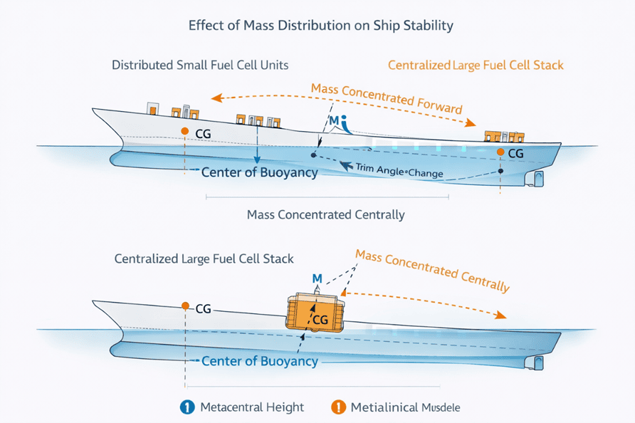
In the maritime context, Weight & Balance corresponds to the trim and stability approach:
- Vertical and longitudinal mass distribution influence trim angle, metacentric height and movement behavior
- The change from „many small“ to „few large“ units leads to more concentrated masses
- Shifts in the center of gravity can be caused by the housing, air routing or installation positions
- Redundancy concepts are changing fundamentally
Early target definitions (system mass, installation locations, permissible trimming windows) and continuous mass tracking are therefore essential.
Risks & decision relevance
Three key risks determine the valuation:
- Scaling risk: Large active areas increase requirements for gas distribution, thermal management and tightness
- Integration risk: Less complexity, but higher requirements for handling, exchange and structural integration
- System risk: hydrogen storage and security architecture continue to dominate volume and mass
The „record stack“ is therefore an important technological step - but not a plug-and-play solution for maritime decarbonization.
Practical conclusion for development projects
- Do not optimize kW per stack, but kW per system complexity
- Explicitly model secondary masses (thermal, housing, cabling, media)
- Define packaging, maintenance and replacement concepts early on in CAD
- Establish mass and CG/trim control at an early stage and continue iteratively
For further information please contact us here: TGM Contact
Sources
- Ingenieur.de: „Hydrogen propulsion from Ulm: This fuel cell stack for ships is the largest in the world“ (02.04.2026)
- ZSW: „Hydrogen power for the maritime energy transition